Blink an LED

This guide provides step-by-step instructions for learners to wire and program a minimal Arduino-compatible Shrimp from scratch.

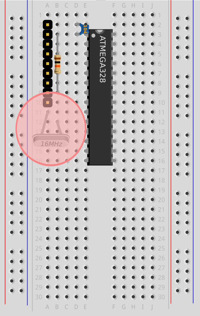
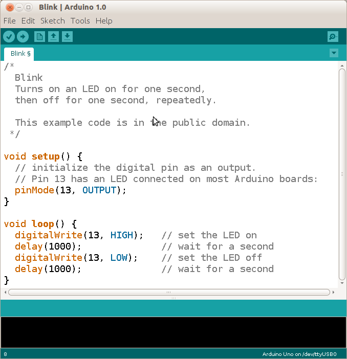
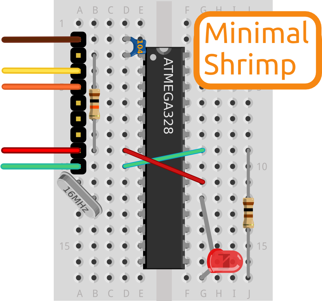
For orientation, see the Blink project page. The completed build should look like the diagram on the left. A successful build will flash its LED rhymically on for a second then off for a second, forever. This proves your core circuit is a good foundation for our other projects or any other project from the Arduino community.

To source parts, order pre-bagged kits from @ShrimpingIt online, or raw components in bulk direct from our wholesalers.

If you think we can improve our guide, please report an issue or email us.

Get your breadboard and Shrimp components, your laptop and favourite beverage, and click on the next step

Meet your breadboard

With a solderless breadboard you make circuits by pushing wires into holes, instead of soldering.

A metal rail behind each 5-hole row grips the legs of inserted components, connecting the 5 holes electrically. Note the central gap from top to bottom. Components in rows above, below or across the gap are separate from each other.

The 400 tie-point solderless breadboard shown has four 'power rails' as columns down the sides. Power rails' holes are misleadingly also grouped into 5, yet holes in a single column are actually all connected to each other. The columns are usually wired Red to 5V (plus, or power) and Blue to 0V (minus, or ground); two very commonly-used connections.

Our guide uses the column letters and row numbers from the breadboards we supply, but any 400pt breadboard should do. The layout also works on a mini-breadboard or soldered on stripboard.

Place the breadboard with its central spine vertically, and with row numbers starting from 1 at the top, (if your rows and columns are labelled)

The ATmega chip

The ATmega microcontroller is a black oblong with printed numbers and 28 silver legs. It is the computer at the heart of our Shrimp projects, with inputs and outputs sensing or triggering things in the real world.

The legs can break if you force them in. If they splay out too much, gently press one side of the chip against the table top (14 legs at a time). When the legs are lined up on the correct holes push down softly to slide them in, then finally push down hard to ensure a good connection.

Carefully orient the chip with the half-moon shape at the top, and two empty rows above. Check the legs are aligned with the right breadboard holes. Once aligned, press down so the chip slides fully into the board (about 3mm movement).

100 nF ‘decoupling’ capacitor

Look for a 100 nanoFarad (nF) ceramic capacitor, a small disc with two thin wires coming out of it marked '104'. These have no orientation, each leg is the same as the other.

This ‘decoupling’ capacitor smooths electrical spikes, so the reboot signal sent through to Pin 1 is reliably detected. The chip should reboot only when you request it (e.g. when you’re reprogramming the microcontroller).

The digits 104 show its capacitance in picoFarads in scientific notation. The last figure '4' tells us how many zeroes to add. The capacitance starts ‘10’ and then continues with a further 4 zeroes - 100,000 picoFarads. Since 1000 picoFarads is 1 nanoFarads, there’s 100 nanoFarads in a capacitor marked ‘104’.

Insert the capacitor marked ‘104’ between

  • d3, the top left leg of the chip (pin 1, immediately anticlockwise from the half-moon shape)
  • d2, the empty row immediately above that
10 kiloOhm pull-up resistor

Look for a cylinder with Brown, Black and Orange stripes. Resistors have no orientation. You can't wire them backwards.

The ATMEGA keeps running as long as Pin 1 senses 5 volts. This resistor will be connected to the 5 volt power supply, weakly 'pulling up' Pin 1 to 5 volts. Later, when we connect Pin 1 to 0V without a resistor, (a strong signal) the chip will reboot. On reboot it listens for a new program being uploaded over the orange wire (on power-up if nothing new is sent, it runs the last program sent).

Decode the colored stripes like the '104' capacitor, but with colors instead of digits. Reading Brown=1, Black=0, Orange=3 gives us the number 103. The resistance in Ohms starts ‘10’ with 3 zeroes after - 10,000 Ohms or 10 kiloOhms.

Attach the resistor with Brown, Black and Orange stripes between...

  • row 9 on the breadboard (will be the positive power line, approx. 5 Volts)
  • the top left leg of the chip (pin 1, immediately anticlockwise from the half-moon shape)
9-pin programming header

Find the line of 9 pins encased in black plastic,

A series of wires from our USB module will be used to program and provide power to the Shrimp. This strip of pins is just a convenience to help us get the wiring right.

If you can, keep the strip intact as you slide the 9 pins in. Not all of the 9 pins be used in this circuit, but having all 9 in the right place helps you position everything else.

Push the 9-pin header strip into the top left corner of the board, leaving just one empty row at the top of the board

16 MHz Crystal

A silver box with rounded ends, and two wires, marked 16.000. Both the legs are the same - you can't wire it backwards.

A computer is a bit like clockwork. The first ever digital computer was built using clock-making techniques, with cogs representing numbers! This quartz crystal acts like the clock's pendulum, causing the mechanism to tick along.

The 16.000 indicates the number of back-and-forth movements this crystal generates per second, in megaHertz. One Hertz means once per second, and one MegaHertz means one million times per second.

Insert the crystal with one leg in the row immediately below the 9-pin header, and the other leg in the row below that

Power and Ground wires

Look for one Red and one Green wire, stripped to show silver at each end.

The ATMEGA chip is broken up internally into separate parts, each of which needs a stable power supply. Power and ground wires will soon be attached to the 9-pin header. A red and green wire are needed to connect power and ground across to the correct legs on the right-hand half of the microcontroller.

Connect a Green wire to the last pin of the 9-pin header, across the chip and up one row.
Connect a Red wire to the second-to-last pin of the 9-pin header, across the chip and down two rows.

Light Emitting Diode

Look for a red or clear dome having two wire legs.

A diode only allows electrical current to flow in one direction. Electricity should flow into the long leg and out of the short leg. Round LEDs also have one slightly flatter side, which corresponds with the short, negative leg of the LED.

Insert an LED, inserting the long leg to the row below the Red wire (on the right hand side of the chip - power, or 5Volts) and the short leg in the first empty row below the microcontroller.

100 Ohm 'current-limiting' resistor

Look for a brown or blue cylinder with a wire at each end, with strips of Brown, Black, Brown. This has no orientation, and can be attached either way round.

Our circuit is running at approximately 5 Volts, and LEDs are rated around 1-2 Volts. This resistor is connected in series with the LED, limiting the amount of electricity flowing to prevent the LED from overheating and destroying itself. Some of the voltage will be used up by the resistor, and only a suitable share of it is applied across the LED.

For an explanation of the coloured stripes, see the earlier section describing the 10kiloOhm pull-up resistor.

Insert the resistor between the short leg of the LED, and the row containing the Green wire on the right hand side of the chip (ground or 0Volts)

USB to UART, (CP2102)

Look for a green or blue-coloured circuit board with a USB connector at one end and 6 pins at the other end. For ease-of-use, leave the rainbow coloured wires bonded together.

This device enables your laptop to communicate with the Shrimp, e.g. to upload your code with the free Arduino IDE, or to send and receive data while the Shrimp is running your code.

Attach the rainbow wires from the 9pin header to the CP2102's labelled pins like…

  • Red -> 5V
  • Orange -> RXD
  • Yellow -> TXD
  • Green -> GND
  • Brown -> DTR

N.B. For ancient Baite CP2102 modules (with DTR label hidden away on the back and pin attached on the side) exchange TXD and RXD

Upload the ‘Blink’ program

Go to the system configuration page to set up your laptop, installing the Arduino IDE, the drivers for the CP2102 UART and the @ShrimpingIt example sketches.

Click File=>Examples=>Basics=>Blink in the Arduino IDE to load the 'Blink' code. 'Blink' is a standard test for Arduino-compatible boards (and learners).

To compile the code and upload it to your Shrimp, click the right-pointing arrow, the menu item File=>Upload or press the CTRL+U key combination (these all do the same thing)

The circuit should be flashing on and off the LED with a delay of exactly one second. Otherwise, check your wiring steps, your laptop configuration and finally our troubleshooter

Configure your machine for Shrimp development
Load ‘Blink’ from File=>Examples=>Basics=>Blink
Choose File=>Upload to upload the program.
You should see rhythmic blinking (e.g. if the lights do not flash, or flash irregularly and then go out, something hasn't worked).

Success: Start Coding!

You should now have a working Shrimp! The LED should be flashing on and off rhythmically once a second. Can you make sense of each line in the code to see how?

Change the code to prove you can send new behaviours to your microcontroller (CTRL+Z to reverse your changes). For example find a line with delay(1000); (a 1000 milliseconds delay) and change it to delay(100);. What happens after you Upload the new code? Change both delay commands to 100. What happens then?

Set both delay commands to 1 millisecond, and the LED flashes on and off so quickly you can't see it. However, it's off half the time, so it is 50% as bright. Can you make the LED appear with 25% brightness or 10% brightness? How?