Building the LED Clock

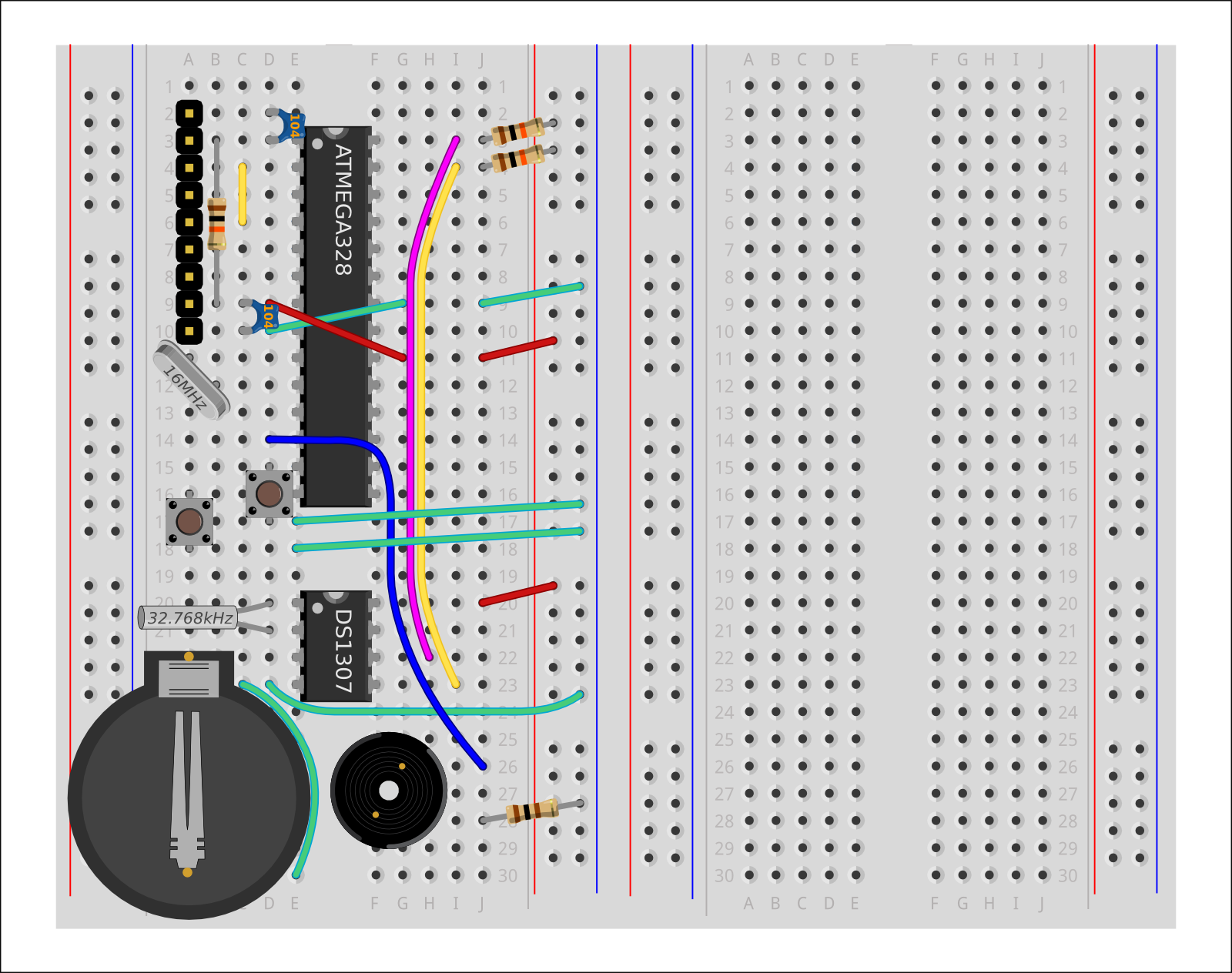
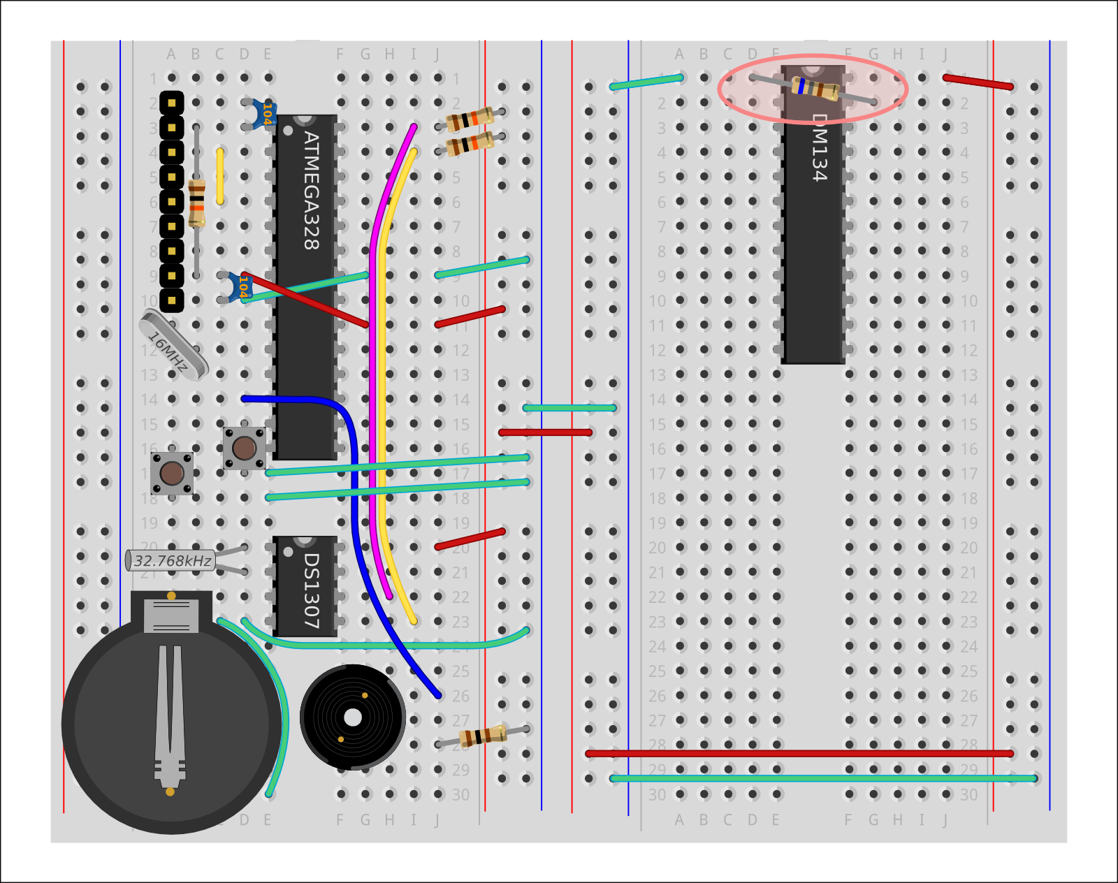
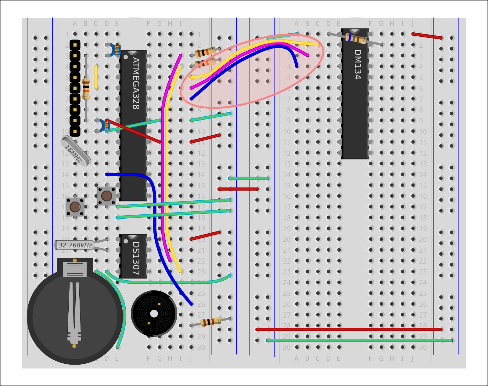
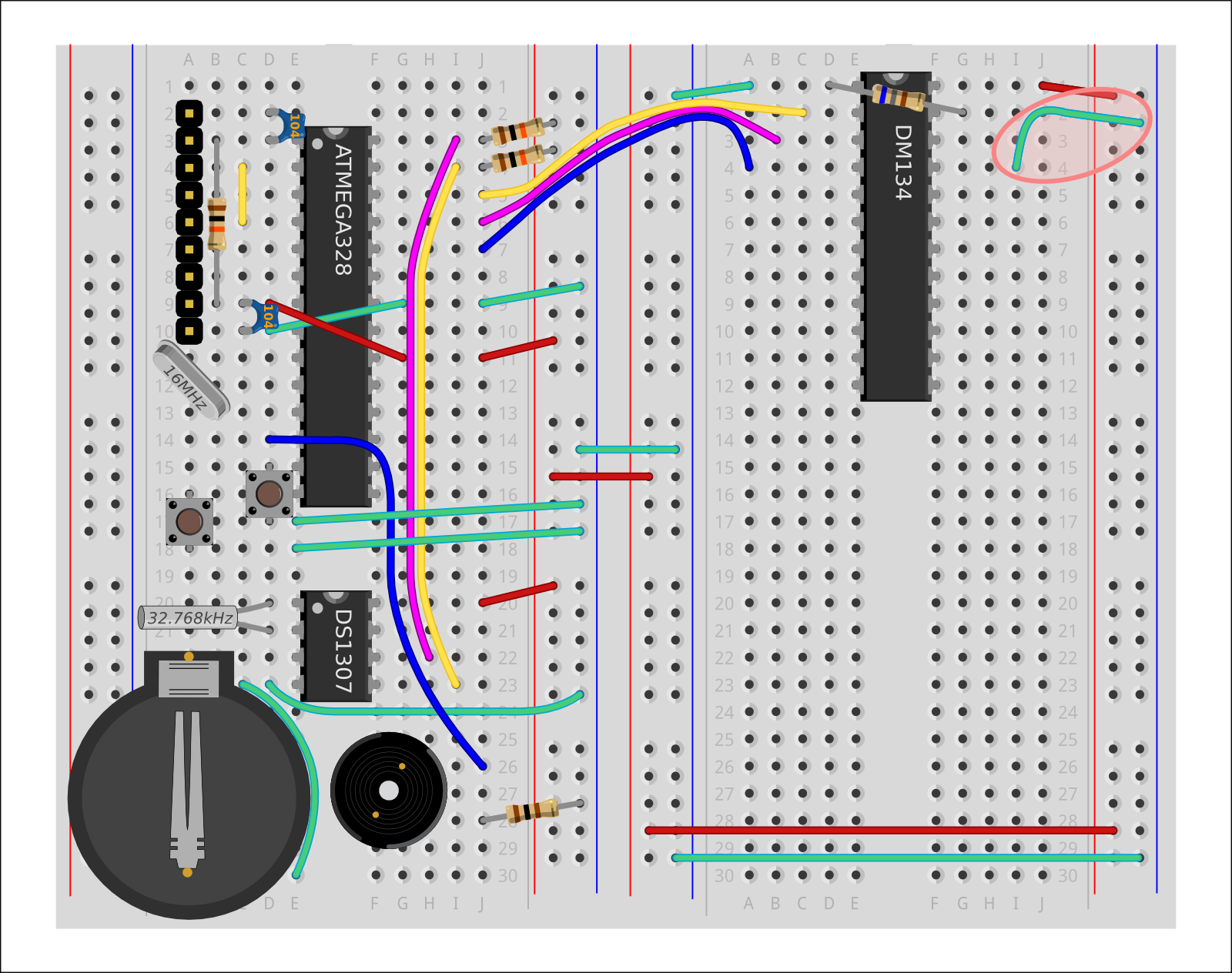
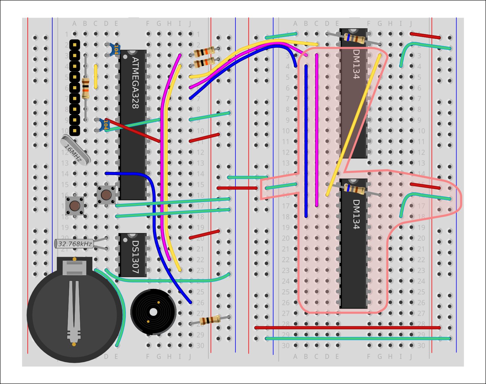
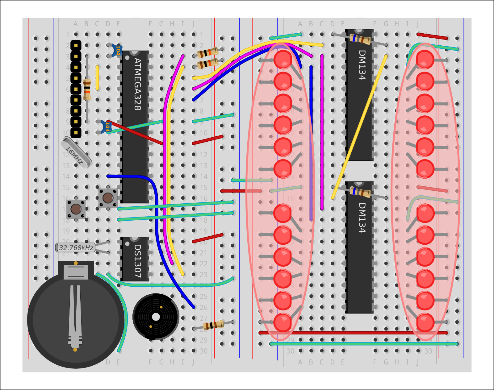
This guide provides details for learners to wire, program and configure their first @ShrimpingIt digital clock project. It incorporates two LED driver chips which control ultrabright LEDs in a layout which can be programmed as a Word Clock or a Unary Clock. For general orientation, see the LED Clock project page. The completed build should replicate the image shown.

For convenience, pre-bagged kits are available to order from @ShrimpingIt online. If you do not wish to buy from us, information is provided for you to source commodity parts direct from electronics wholesalers.

Getting started

Before embarking on the Alarm Clock, you should have successfully completed the Alarm Clock build. This build uses the Alarm Clock circuit as its starting point.

An extra breadboard

The 24 LEDs in the display will be laid out, with special chips to drive them, on an extra breadboard, which we will refer to as the LED Display breadboard.

Later, this will be attached to the (previously constructed) Alarm Clock breadboard with just four wires, two for power (+5V and 0V) and two for receiving LED control data (Clock and Data).

The breadboards can be oriented in various ways, as long as the four wires are attached. For example, the breadboards could be attached back-to-back to fit compactly inside a housing when the build is complete.

However, to make the build simple, we will first attach the new breadboard to the right of the previous Alarm Clock breadboard, using the in-built docking mechanism.

  • ***Attach a new breadboard to the right of the Alarm Clock breadboard. The new breadboard's lugs should slide into slots at the rear of the old breadboard
Extra breadboard power rails

Both power rails of the second breadboard will be heavily used, powering up the LED driver chips, and supplying each of the 24 LEDs.

We therefore need to connect red and green wires across from the power rail of the Alarm Clock breadboard, and in turn wire the left and right power rails of the second breadboard together.

  • Attach a Red wire from the right-hand Red +ive column of the Alarm Clock breadboard to the left-hand Red +ive column of the LED Display breadboard, roughly below the row numbered 15
  • Attach a Green wire from the right-hand Blue -ive column of the Alarm Clock breadboard to the left-hand Blue -ive column of the LED Display breadboard, roughly below the row numbered 16
  • Attach a Red wire from the left-hand Red +ive column of the LED Display breadboard to the right-hand Red +ive column of the LED Display breadboard, starting just above row 15, and finishing just below row 15.
  • Attach a Green wire from the left-hand Blue -ive column of the LED Display breadboard to the right-hand Blue -ive column of the LED Display breadboard, starting just above row 16, and finishing just below row 16.
First DM134 LED Driver

The DM134 LED driver chip will be used to switch on and off the LEDs we're about to attach. Each chip is actually capable of controlling up to 16 LEDs, but we're only using 12 on each, for a total of 24 lights.

The DM134 chip will need a power connection, wires to receive LED lighting commands from the Shrimp's microcontroller, and a resistor to control how much power to give the LEDs.

Just like the ATMEGA328P-PU and the DS1307, the DM134 chip has a half-moon stamped at one end. Pins are numbered anticlockwise, starting from the half-moon.

The first driver chip should be placed in the same orientation as all the other chips, straddling the right-hand LED Display breadboard and positioned as far up as it can go.

  • Insert the first DM134 chip with the half-moon shape at the top of the breadboard. Pin 1 (the top-left pin, anticlockwise from the half-moon) should be in row 1, and pin 12 (the bottom-left pin) should be in row 12.
Power for the DM134

Pin 1 needs a connection to ground and Pin 28 (all the way anticlockwise from the half-moon) needs a connection to the 5V supply.

  • Attach a Green wire from a1 to the (Blue) left-hand -ive power rail
  • Attach a Red wire from g1 to the (Red) right-hand +ive power rail
A 'Reference' Resistor

You may recall from the Blink build that attaching LEDs directly to 5V can make them burn out, so a current-limiting resistor was added between the LED and ground when attaching the Blink LED, to limit the flow of electricity.

A DM134 is known as a 'constant current' LED driver, and you can explicitly limit the current which flows through the LED pins. We simply have to attach a single current-limiting resistor between the DM134's pin 23 and Ground, to tell the DM134 what the maximum current should be. This saves us having to attach current-limiting resistors to every single one of the 24 LEDs.

The correct resistor value can be calculated by looking at theData sheet for the DM134, which shows a helpful graph showing the relationship between the resistor value and the LED current for a 5V circuit. This shows that a 680 Ohm resistor would be appropriate for our LEDs which should only be driven by a current of around 20 milliAmps, that's 20 thousandths of an Amp.

  • Attach a 680Ohm resistor between g2 and d1
DM134 I2C Control Wires

The DM134 can accept instructions to turn on and off specific LEDs over three wires. If the data wire (yellow) is at 5V then a one is being sent. If the data wire is at 0V then a zero is being sent. The clock wire (purple) is pulsed to 5V when a new value on the data wire is ready to be read. Using this clocked serial data stream, a series of ones and zeroes is read into a memory store on the DM134. Finally when the values of all the LEDs have been sent, a Latch wire is pulsed, to tell the DM134 to display the new series, determining which individual LEDs are on or off.

  • Attach a Yellow wire between j5 on the left breadboard and c2 on the right breadboard, connecting the serial 'Data' line
  • Attach an Purple wire between j6 on the left breadboard and b3 on the right breadboard, connecting the serial Data line
  • Attach an Blue wire between j7 on the left breadboard and a4 on the right breadboard, connecting the serial Data line
DM134 Enable Wire

The DM134 has an enable pin. When the pin detects the right signal, it enables itself. Without receiving the right signal, it will do nothing at all.

The required signal is described in the data sheet as an 'Active Low'. That means it's a pin which is normally pulled up to the supply voltage (5V), and needs to be connected to Ground to pull down the pin (to 0V) to activate it.

When enable it is not connected to Ground, then no LEDs will light.

Once you have attached the enable wire the first DM134 chip is fully wired up.

Second DM134 chip

The second chip needs exactly the same connections as shown in the diagram. However, the second chip accepts data not from the ATMEGA chip directly, but from lighting information 'overflowing' from the previous DM134. When the ATMEGA sends more than 16 ones and zeroes, the extra information is passed on from the first DM134 to the next one.

  • Attach a Green wire from a15 to the (Blue) left-hand -ive power rail, (connects DM134 Ground Pin to 0V).
  • Attach a Red wire between j15 and the (Red) left-hand -ive power rail, (connects DM134 Power Pin to +5V).
  • Attach a 680 Ohm resistor between d15 and the top-left row (Blue) (providing Pin 23 with a constant current reference)
  • Attach a Yellow wire between g3 on the right breadboard and d16 on the right breadboard, connecting the serial 'Data' line
  • Attach an Purple wire between c3 on the right breadboard and c17 on the right breadboard, connecting the serial Data line
  • Attach an Blue wire between b4 on the right breadboard and b18 on the right breadboard, connecting the serial Data line
  • Attach a Green wire between i18 on the right breadboard and the (Blue) right-hand -ive power rail, (connects DM134 'Active Low' Enable pin to 0V).
24 LEDs

There are a total of 24 LEDs to insert. Each one has one slightly longer leg - the positive leg, into which electrical charge flows to light it up. LED stands for "Light Emitting Diode". A diode is equivalent to a valve - it only allows charge to flow one way. If you attach your LEDs the wrong way round, they will not light up.

The long legs need to be attached to the +ive power rails down the sides of the LED display breadboard, and the short legs should be inserted either side of the DM134 chips in breadboard rows 5,6,8,9,11,12 and 19,20,22,23,25,26. The DM134 will allow current to flow into the pins in these rows, or block current flow, depending on the instructions it receives from the Shrimp's microcontroller.

Follow the pattern of LED wire locations in the diagram. These locations have been selected to allow enough space for the 5mm LEDs to lie next to each other.

Extra Protection

The LED driver chip draws so much current that if all its lights are turned on simultaneously then the sudden demand can trigger problems elsewhere in the circuit. This is a frustrating fault to diagnose because it is occasional, depending on multiple factors.

Unless your USB power supply is very reliable (e.g. a short cable to a high-quality voltage-regulated supply) it's a good idea to have a local reservoir of charge to smooth over these differences.

The 104 ceramic capacitors we use have a very rapid response time, but they cannot hold a great deal of charge. By contrast, the large 10uF electrolytic capacitor is slow to respond, but can store quite a lot of charge. Adding both capacitors together should enable rapid response and a substantial reservoir.

The capacitors will be attached across the power supply from 5V to 0V. The ceramic capacitor has no orientation. The electrolytic capacitor has its positive leg longer than its negative leg, and a strip down its body on the negative side showing minus symbols.

Add a 100 nF ceramic capacitor (marked 104) between h9 and h11 on the left breadboard
Add a 10 uF electrolytic capacitor between i9 and i11 on the left breadboard

Finished, Upload the code!

Now you should be able to upload example code to use the LED arrays as a time display, following these instructions