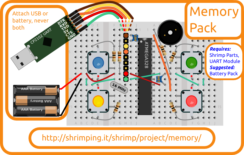
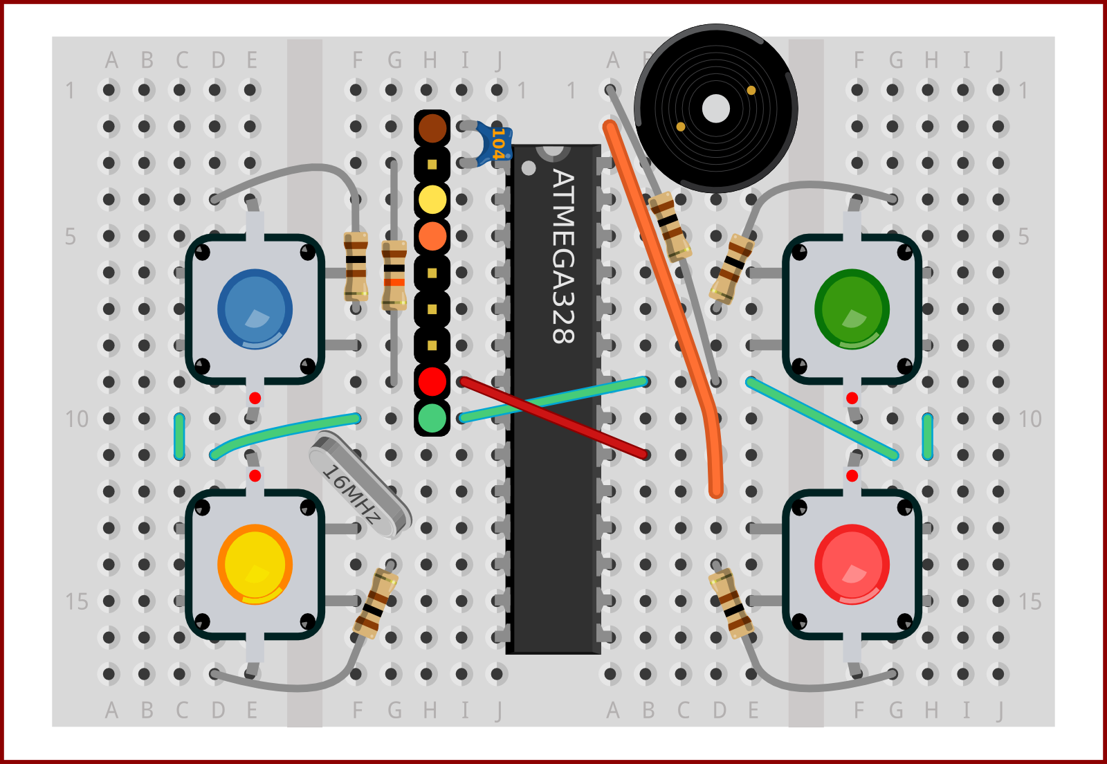
Melodies will play a part in our game, meaning we need to attach an audio output.
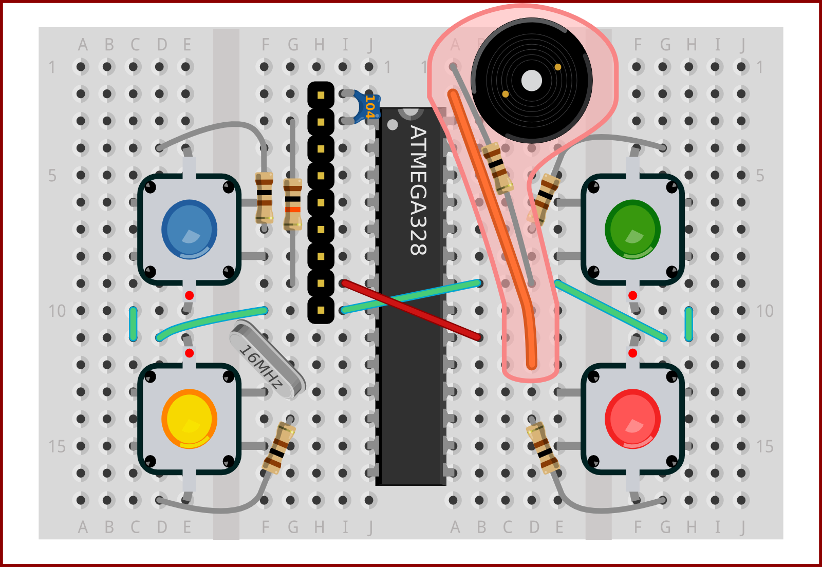
A piezo transducer should be attached with one pin in row 1 and another pin in row 2. Piezos can have slightly different pin separations and can require some force to insert. Take a look from the side to check where the pins are actually entering the breadboard.
The orange wire connects the system to a PWM capable pin. Our library will generate different tones according to melodies specified in the Arduino code, using RTTTL (Ring Tone Text Transfer Language - a format originally used by old mobile phones).
A resistor will complete the circuit, providing a connection back to ground, but also helping to limit the current used by the Piezo. This restricts the volume and helps to maintain the stability of the circuit's power supply when the melodies are playing.
Insert the Piezo transducer with one pin in row 1 and another in row 2 (as illustrated)
Add an orange wire from d12->a2
Add a 100 Ohm resistor from d12->a2

