Wiring Persistence of Vision

This guide provides details for learners to wire, program and configure a @ShrimpingIt Persistence of Vision (POV) project. For general orientation, see the POV project page. The completed build should replicate the image shown on the left, and runs a range of example behaviours.

For convenience, pre-bagged kits are available to order from @ShrimpingIt online. If you do not wish to buy from us, information is provided for you to source commodity parts direct from electronics wholesalers.

Getting started

Before embarking on the Alarm Clock, you should have successfully completed the Blink build. This build uses the Blink circuit as its starting point.

Remove surplus parts

You can remove the Blink LED and resistor as these are not used in the circuit, and it will be easier to wire the circuit with them out of the way.

Right-hand Ground Rail

Find the power rails of your 400 point breadboard. They are four very long contacts running in pairs down each side of the breadboard.

Although the vertical columns of holes are presented in five-hole-groups, each column actually contains just one contact. Any wire inserted in the column is connected to every other wire in the same column, even if it's inserted in a different five-hole-group. Note this is completely different to breadboard rows, where every group of five is isolated from every other.

They are called power rails because two crucial connections are commonly needed for components to get power, 5V (VSS or VCC) and 0V (Ground or GND). The columns often have a red or blue line running alongside them. We will follow the convention that the column with the blue line should be used for a ground connection (0V).

We will only be attaching the ground rail on the right of our breadboard. This column will provide a ground connection for the short legs of our LEDs. The LEDS will get a positive voltage from their long legs, which will be connected to the software-controllable breadboard rows next to the ATmega chip.

Add a Green wire from h9 to the Blue (-ive) power rail on the right hand side of the breadboard

Light Emitting Diodes

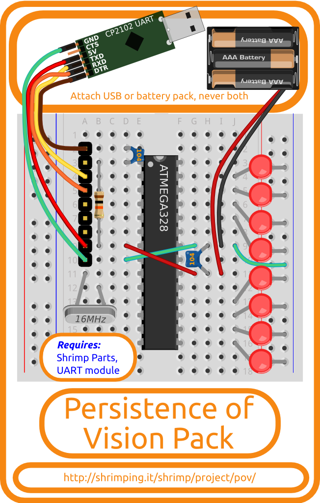
To paint text and images in the air, we will be turning on and off individual Light Emitting Diodes (LEDs) really fast.

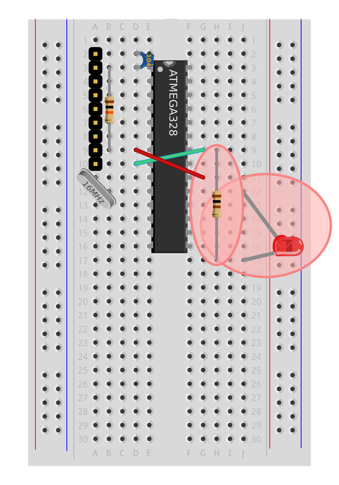
A diode is like a one-way-valve for electricity. It allows current to flow through it in one direction, but blocks it in the other direction. An LED is a Light-Emitting Diode, so if we wire them the wrong way round, no current will flow, and they won't light up.

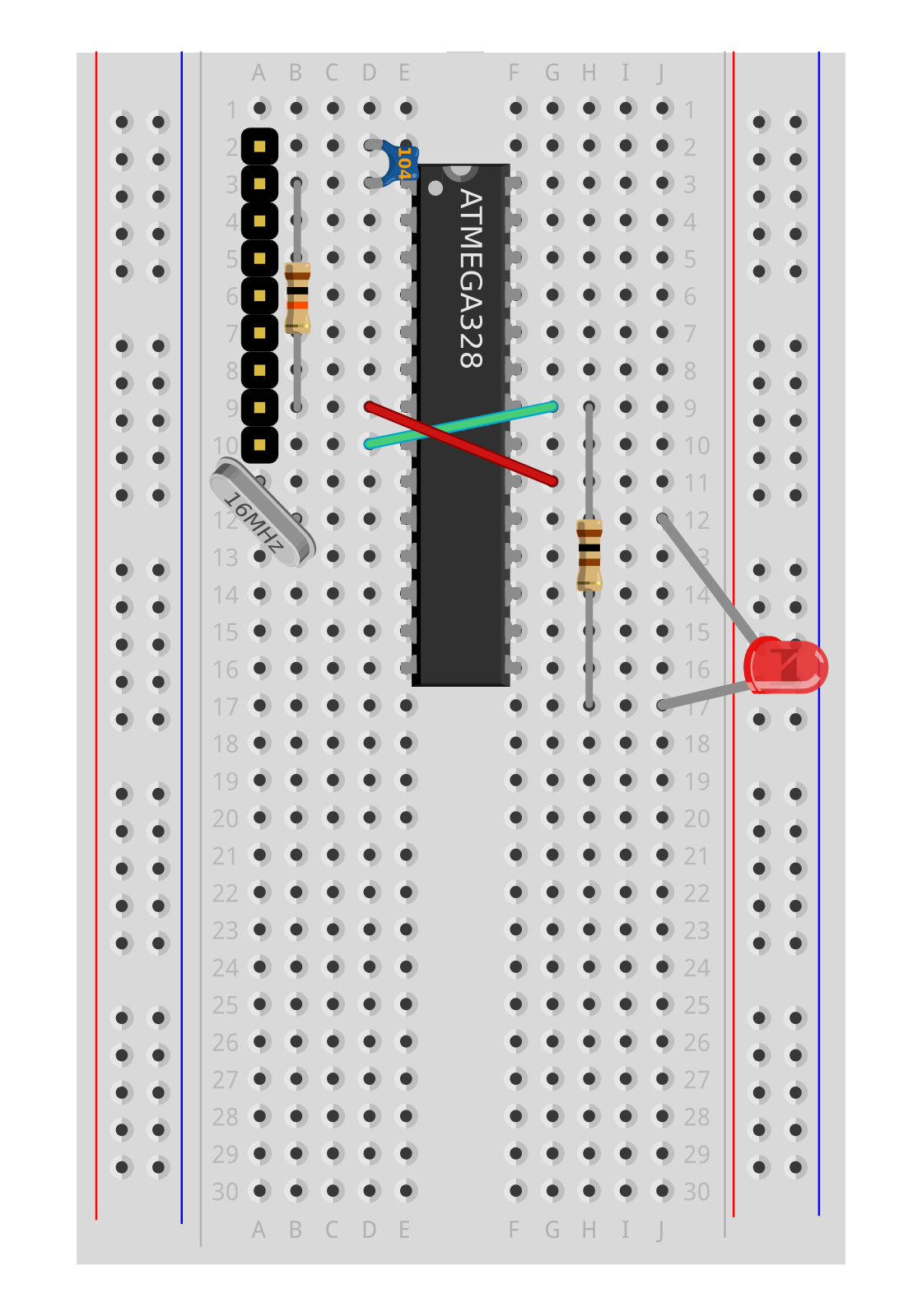
LEDs have two clues showing their orientation. The positive leg is longer than the ground leg. Also if you look from above, it's not entirely round, and is slightly flattened near the negative leg (this helps if the legs are bent or cut).

To get them the right way round, we need to insert each LED so it has a short ground leg in the Blue power rail (providing a 0V connection) and a long leg next to a pin of the ATmega chip (allowing the software on the ATmega chip to control when they get current and light up).

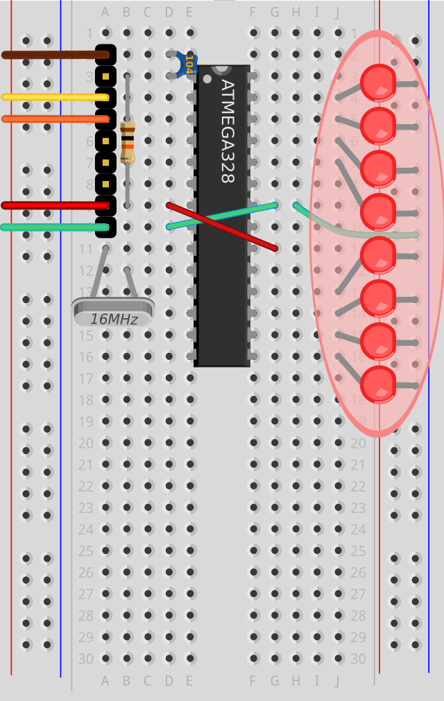
After adding all the LEDs, arrange the heads touching each other and in a straight line. The LEDs are brighest only in a narrow beam (15 degrees), so getting them to point out parallel to each other is useful, and you can bend the heads of the LEDs parallel to get an even illumination in the end.

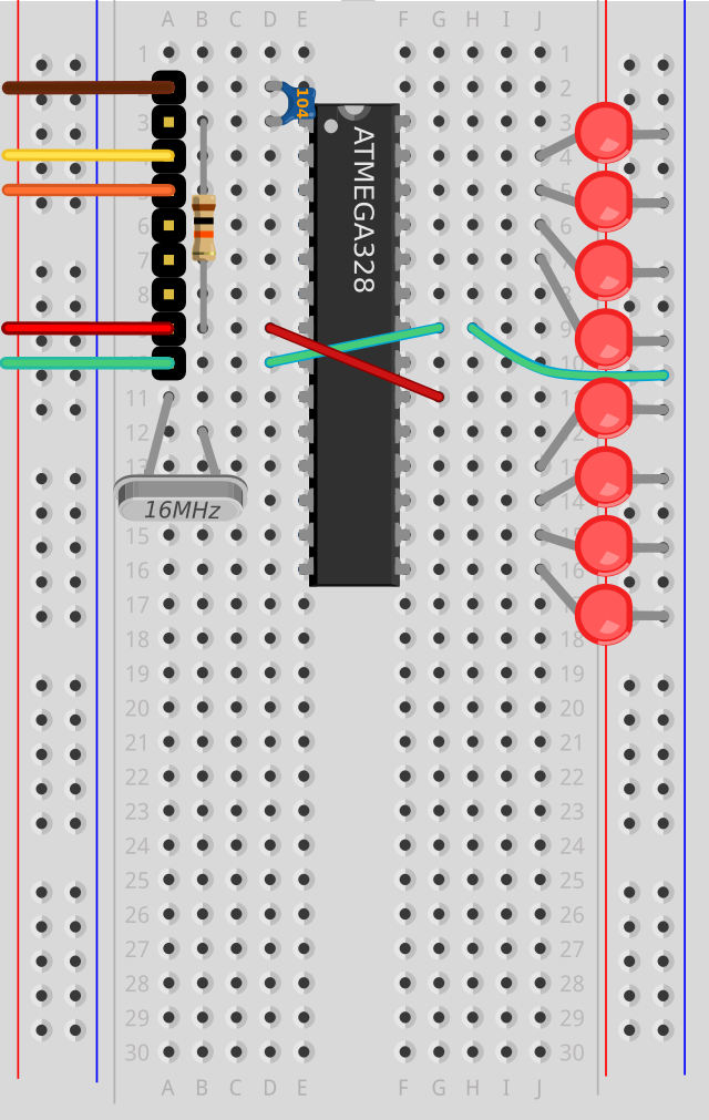
Add LEDs in a column of 8, with the long legs in j4, j5, j6, j7 and j13,j14,j15,j16 and the short legs pushed into the Blue (0V) power rail on the right of the breadboard

Upload

Now the circuit is complete, you should be able to visit the programming page for this project to upload some test programs. This includes a step-by-step programming progression with six increasingly complex test examples, but you can skip to the next step for the high-impact demo at the end, painting your name or your icon design in the air.

POV Demo

After programming, you are ready to demo your Persistence of Vision circuit. You can grip the battery pack behind the breadboard to provide power as you wave it in the air.

It can be convenient to have both the battery pack and the USB module wired in at the same time so you can program, then test, then reprogram and retest. However make sure only one is actually powered up. This means; switch off the battery pack before plugging USB into the computer, unplug USB from the computer before switching on the battery pack.

Upload the Pov07PaintText program.
Unplug the USB module from your computer
Attach the battery pack with the Black ground lead to i9 and the Red +4.5V lead to i11 and switch it on
Grip the battery pack behind the breadboard as you wave it in the air