Wiring an LCD Clock

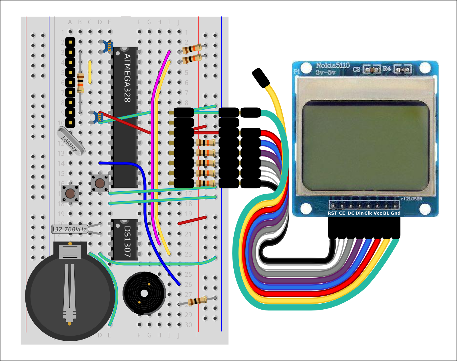
This guide provides details for learners to wire, program and configure a @ShrimpingIt digital clock project. It incorporates a 84x48 pixel liquid crystal display (the same as the Nokia 5110). It can therefore be programmed to display text, numbers or simple line-art as part of a time-driven behaviour. For general orientation, see the Liquid Crystal Clock project page. See a demo here

For convenience, pre-bagged kits are available to order from @ShrimpingIt online. If you do not wish to buy from us, information is provided for you to source commodity parts direct from electronics wholesalers.

Getting started

Before embarking on the Alarm Clock, you should have successfully completed the Alarm Clock build. This build uses the Alarm Clock circuit as its starting point.

Attach Adaptor

We have manufactured a simple adaptor which avoids the complexity of an extra breadboard, since the wiring job for the Liquid Crystal screen is very basic. The modules simply have 5 'series' resistors for protecting the 3.3V signal pins from the 5V signal generated by the Arduino and two wires, red and green for power and ground.

An alternative to this is to wire to an improvised adaptor with a 170 point breadboard using 5x 10kOhm resistors and two ordinary wires between the ATmega pins and the LCD pins, such that the wiring is electronically equivalent to the adaptor.

Push the crimped adapter into the breadboard between row 9 and row 16 on the right hand side of the breadboard, checking the red and green wires line up

Rainbow cable

Once the adaptor is in place, you should be able to connect a rainbow cable to wire up the adapter to the liquid crystal screen. Colours of the wires don't matter (they are just conducting wires), but it's important that they connect the right pins.

There is deliberately a spare wire between the GND (0Volts, green) and the VCC (+5Volts, Red), here shown in yellow, which you might wish to use for controlling the backlight of the LCD screen, but this is not currently included in our programs.

Attach one end of the rainbow cable to the adaptor

Attach Screen

Now attach your LCD screen. Verify your wiring by following the route of the coloured wires in the graphic on the diagram to check the Liquid Crystal display is properly wired before powering up the circuit. Ensure no wires cross over (they should be in the same sequence at both ends), and that the VCC and GND connectors on the LCD connect to the Red and Green wires crossing the ATmega.

Attach the other end of the adaptor to the Nokia screen.