
Examples for the Persistence of Vision (POV) Circuit
The POV programming examples help learners approach the basics of the Arduino language which runs on the Shrimp, with immediate results visible on their POV circuit.
Alternatively skip straight to the high impact demonstrators to push the limits of your Persistence of Vision circuit and to wow friends and family.
- Arduino language examples
- High-impact demonstrators
Installing the examples
You can upload the programs described below to your circuit once you have completed the Programming Shrimps instructions to install the relevant software on your laptop.
Once properly installed, the sketches described appear in the File=>Sketchbook=>shrimpingit=>pov menu. All the examples below run on the same circuit, which you can construct following the build instructions
Using true and false to control 8 lights
To begin, let's control the 8 LEDs to produce a static pattern by running the Pov01PatternFixed sketch.
The key part of the code is shown below, which controls eight digital output pins (pins which can be on or off) by 'writing' a value of true or false.
//turn on selected LEDs
digitalWrite(9,  true );
digitalWrite(10, false);
digitalWrite(11, true );
digitalWrite(12, false);
digitalWrite(A1, true );
digitalWrite(A2, false);
digitalWrite(A3, true );
digitalWrite(A4, false);
In the default pattern, every odd light is illuminated, and every even light is extinguished. Try changing some of the true or false values to prove you can turn different lights on and off.
Storing a pattern in the 8 bits of a byte
The next sketch called Pov02PatternStored shows how to produce the same pattern, but by reading bits from a byte instead.
byte pattern = 0b10101010;The byte called pattern contains either a one or a zero in each of its eight positions to determine whether each light is on or off, (the prefix 0b tells us that the byte is written in binary, as a series of bits). Try changing the 1s and 0s (a byte has to have exactly eight of them) and uploading to prove you can turn different lights on or off.
Instead of the hard-coded true or false value for each LED in the last sketch, a calculation like pattern & 0b00000001 is used to inspect a single bit at a time.
//check which 'bits' are set in the byte called 'pattern'
digitalWrite(9,    (pattern & 0b00000001) != 0);
digitalWrite(10,   (pattern & 0b00000010) != 0);
digitalWrite(11,   (pattern & 0b00000100) != 0);
digitalWrite(12,   (pattern & 0b00001000) != 0);
digitalWrite(A1,   (pattern & 0b00010000) != 0);
digitalWrite(A2,   (pattern & 0b00100000) != 0);
digitalWrite(A3,   (pattern & 0b01000000) != 0);
digitalWrite(A4,   (pattern & 0b10000000) != 0);
In the calculation, we are using the bitwise & operator. It creates a new byte (sequence of eight bits) from two other bytes.
In this case, it takes the two bytes pattern AND 0b00000001, passing on a 1 bit only where BOTH pattern AND 0b00000001 have a 1. So if either of them has a 0bit in some location, the resulting byte will have a 0 bit there.
The byte 0b00000001 has zeroes in all but one location, so if pattern has a 0 bit at that spot, the result of the bitwise & will be 0x00000000, (the byte representing the number zero).
The expression != 0 means "not equal to" zero. The calculation (pattern & 0b00000001) != 0 is therefore true if and only if the first bit of pattern is a 1.
Each bit is examined in turn, the first bit 0b00000001, then the second bit 0b00000010, then the third bit 0b00000100 and so on until all eight LEDs have been set to either on or *off".
Traversing the byte pattern with a while loop
In Pov03PatternWhile, instead of having separate lines of code for every LED, we use a while loop.
The key parts of this code are shown below. To avoid writing the instructions eight times, a single set of instructions is executed eight times with parameters that change each time.
The steps shown run one after the other. However, note the indented steps inside the while loop are repeated while the bitCounter is less than 8.
int pinNumbers[] = { 9,10,11,12,A1,A2,A3,A4 };bitCounter = 0;
bitValue = 0b00000001;
while(bitCounter < 8){
digitalWrite(pinNumbers[bitCounter], (pattern & bitValue) != 0);
bitValue = bitValue * 2;
bitCounter = bitCounter + 1;
}A pinNumbers array contains the pin numbers to control. Array values are retrieved using a subscript in square brackets, for example pinNumbers[0] gets the first entry, (the stored value 9), or pinNumbers[7] the eighth and last entry, (the stored value A4).
Note, in programming, counting up to eight begins with 0 and finishes with 7!
To begin, the bitCounter is assigned the value zero. We use bitCounter as a subscript to retrieve the next pin from the pinNumbers array like pinNumbers[bitCounter]. The LED is turned on or off with the digitalWrite instruction using the same calculation as before, but with a bitValue that changes. After updating the LED bitCounter = bitCounter + 1 increases the bitCounter. This ensures a different bit (and a different LED) is processed the next time round. This means the bitCounter will be 0 then 1 then, 2,3,4,5,6,7 before escaping the while loop.
The variable bitValue is initially assigned the value 1. After we have turned on or off the LED, the instruction bitValue = bitValue * 2 multiplies bitValue by two. This means the bitValue will adopt the value 1 then 2 then 4,8,16 and so on. This is equivalent to the binary series 0b00000001, 0b00000010, 0b00000100, 0b00001000, 0b00010000 etc. visible in the stored pattern example.
Writing a function to traverse the pattern
In Pov04PatternFunction, we remove the duplication in the routine called loop. We put the lighting steps in their own routine, called setLights.
void setLights(byte pattern){
  bitCounter = 0;
  bitValue = 1;
  while(bitCounter < totalBits){
    digitalWrite(pinNumbers[bitCounter], (pattern & bitValue) != 0);
    bitCounter = bitCounter + 1;
    bitValue = bitValue * 2;
  }
}
Then in the simplified loop routine, we trigger the setLights steps twice.
void loop() {
  setLights(pattern);
  delay(1);
  setLights(empty);
  delay(2);
}
Painting a smiley face in the air
Previously we were visiting a sequence of bits, and setting the lights to a given pattern. Now we go 'up a level' by doing the same thing for a sequence of patterns. If we upload Pov05SequenceSmiley and attach a battery pack, then waving it in the air should paint a smiley face.
The key parts of this code are shown below. The byte array called patternSequence contains a series of bytes which map to vertical columns making up a smiley face.
byte patternSequence[] = {
0b00111100,
0b01001110,
0b11011011,
0b11011111,
0b11011111,
0b11011011,
0b01001110,
0b00111100
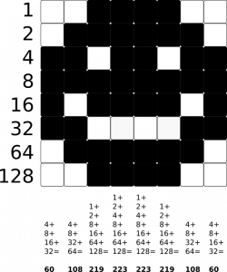
};If you inspect the 1s and 0s in the byte array, you can see the image below, tipped to the right (each byte is a vertical column, starting from the left side)...
Painting the Arduino™ logo in the air
Just for fun, we do the same thing with a different pattern - the Arduino Logo with our sketch Pov06SequenceArduino. Of course this is best done with Blue LEDs!
byte patternSequence[] = {
  0b00111000,
  0b01000100,
  0b10010010,
  0b10010010,
  0b10010010,
  0b01000100,
  0b00101000,
  0b00010000,
  0b00101000,
  0b01000100,
  0b10010010,
  0b10111010,
  0b10010010,
  0b01000100,
  0b00111000
};
This sketch should cause the image below to be painted in the air...
![]()
Painting your text in the air
Our last demonstration sketch is the best. Pov07PaintText incorporates the 8-bit font from a Commodore 64 into an Arduino sketch, so learners can paint their choice of text in the air.
In our example code, we have replaced the original font's $ symbol with the smiley face sequence, showing how to combine your own icons with text messages.
String message ="HACK $";Try looking for the above fragment of code (try CTRL+F to find the word 'message').
Then change HACK to show the text you prefer. Be careful to keep the keyword String, the = symbol, quote marks and semi-colon in place otherwise a compiler error will be reported.
If you get really stuck after making code changes, try mashing CTRL+Z (undo) or just delete everything and copy paste the original code back in place.

Exploring our examples
All the code examples for the POV circuit can be browsed on the web at https://github.com/ShrimpingIt/projects/tree/master/sketchbook/shrimpingit/pov
If you want to install our sketches to upload them to your own @ShrimpingIt kits, follow these instructions to configure your computer.
Future developments
Why not add a tilt-switch to 'reverse the polarity' so the circuit can tell whether it is moving from left-to-right or from right-to-left?
Attach a soldered version of the circuit securely to a bicycle wheel or wind turbine, or as a Dance Messenger attached to your shoe to paint text as you move.